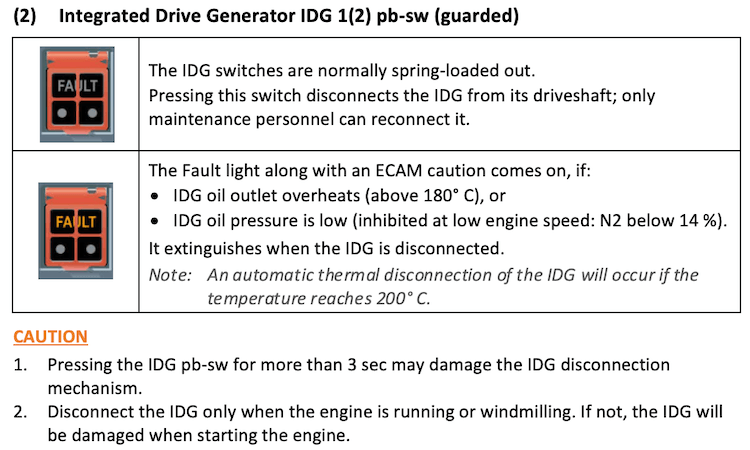
general
In normal operations, the generation and distribution of electrical power is fully automated and does not need any interaction.
The electrical power system consists of:
- A three-phase 115/200V 400 Hz constant frequency AC system and,
- A 28V DC system.
The electrical system is constituted of two engine-driven generators and one APU generator. Each generator can provide AC power to all electrical bus bars. A part of this AC power is converted into DC power for certain applications.
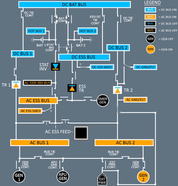
A-320 Electrical System
ac power generation
Main Generators
Two engine-driven AC generators (GEN 1 & GEN 2), supply aircraft electrical power. Each generator can supply up to 90 KVA of three phase 115/200V 400 Hz power.
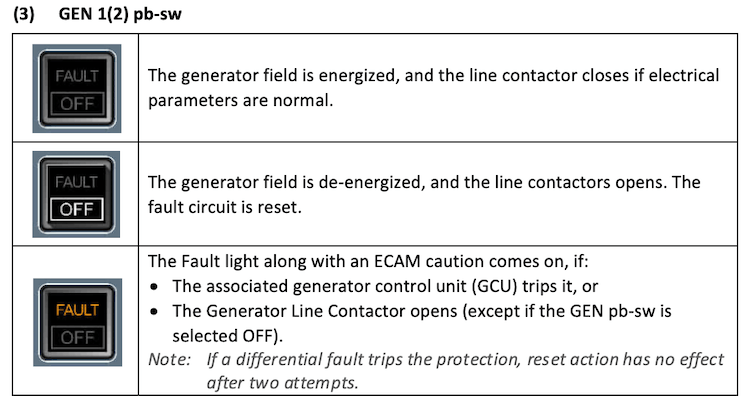
Each generator supplies its associated AC BUS via its Generator Line Contactor (GLC 1 & GLC 2). Two Generators Control Units (GCU) control the output of their respective generator by:
- Controlling the frequency and voltage of the generator output and,
- Protecting the network by controlling the associated GLC.
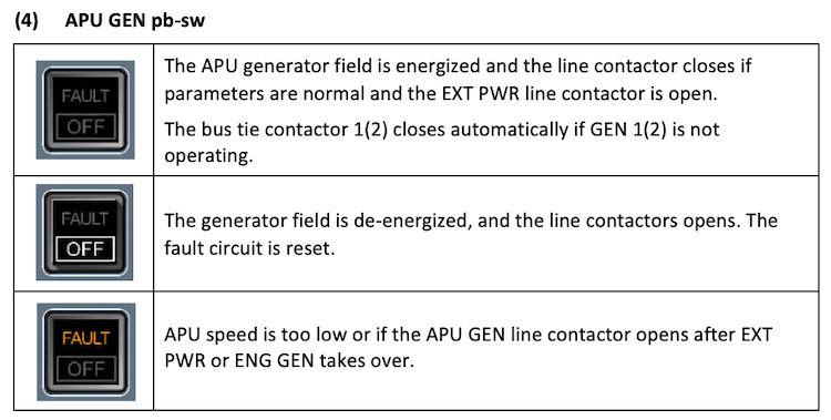
APU Generator
A third generator (APU GEN), driven directly by the APU and producing the same output as each main engine generator, can replace either or both main engine generators at any time.
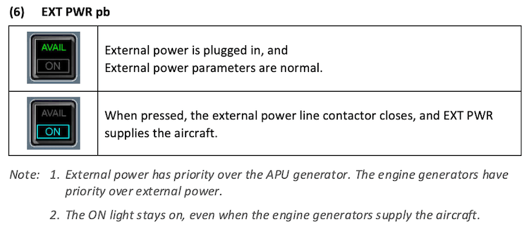
External Power
A ground power connector near the nosewheel allows ground power to be supplied to all busbars.
A Ground Power Control Unit (GPCU) protects the network by controlling the external power contactor.
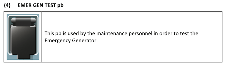
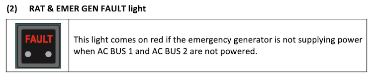
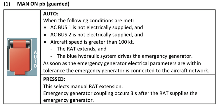
Emergency Generator
If all main generators fail, the blue hydraulic circuit drives an emergency generator that automatically supplies emergency AC power to the aircraft electrical system. This generator supplies 5 KVA of three-phase 115/200V 400 Hz power. A Generator Control Unit (GCU) :
- Keeps the emergency generator at a constant speed,
- Controls the generator's output voltage,
- Protects the network by controlling the emergency generator line contactor, and
- Controls the emergency generator start-up.
Static Inverter
The static inverter transforms DC power from BAT 1 into 1 KVA of single-phase 115V 400 Hz AC power, which is then supplied to part of the AC essential bus.
When the aircraft speed is above 50 kt, the inverter is automatically activated, if nothing but the batteries are supplying electrical power to the aircraft, regardless of the BAT 1 and BAT 2 pushbutton positions, but when the speed is below 50 kt, the inverter is activated only if the BAT 1 and BAT 2 pushbuttons are both set at auto position.
DC POWER GENERATION
Tranformer Rectifiers
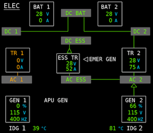
Two main Transformer Rectifiers (TR 1 &TR 2), supply the aircraft's electrical system, with up to 200 A of DC current. TR 1 supplies DC BUS 1, DC BAT BUS, and DC ESS BUS. TR 2 supplies DC BUS 2.
A third (identical) transformer rectifier (ESS TR), can power the essential DC circuit from the emergency generator, if the engine and APU generators all fail, or if TR 1 or TR 2 fails. Each TR controls its contactor by internal logic.
Main batteries
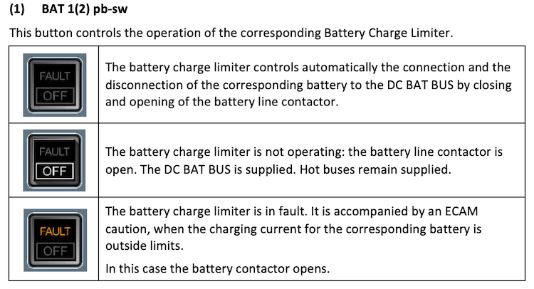
The two main batteries, each with a normal capacity of 23 Ah, are permanently connected to the two HOT buses. Each battery has an associated Battery Charge Limiter (BCL) which, monitors battery charging and controls the connection and the disconnection of the corresponding battery to the DC BAT BUS by closing and opening of the Battery Line Contactor.
In normal configuration, most of the time the batteries are not connected to the DC BAT BUS. They connect to the DC BAT BUS in case of:
- APU start (the connection is limited to 3 min when the emergency generator is running).
- Battery charge, when the voltage is below 26.5V. The charging cycle is completed when the battery charge current goes below 4A and, ends immediately on the ground and after a time delay of 30 min during the flight.
- Loss of AC BUS 1 and AC BUS 2 when below 100 kt (EMER GEN is not supplying).
- Battery 1 supplies the AC STAT INV BUS and, if speed is greater than 50 kt, the AC ESS BUS.
- Battery 2 supplies the DC ESS BUS.
NOTE 1
If the aircraft has not been electrically supplied for 6 h or more, check the batteries voltage (select BAT 1 & 2 OFF and check that voltage is above 25.5V). If battery voltage is below 25.5V, a charging cycle of about 20 min is required:
- Select BAT 1 & 2 AUTO and EXT PWR ON. Check on ELEC SD page, that the battery contactor is closed and the batteries are charging.
- After 20 min set BAT 1 & 2 OFF and check if voltage is above 25.5V.
NOTE 2
If the APU is started on batteries only, it should be started within 30 min after the selection of batteries to AUTO.
NOTE 3
Battery automatic cut-off logic prevents the batteries from discharging completely when the aircraft is on the ground.
CIRCUIT BREAKERS (C/B)
The aircraft has two types of C/Bs:
- Monitored (green): When a C/B is out for more than 1 min, the ECAM C/B TRIPPED caution message is triggered indicating the location of the affected C/B.
- Non-monitored (black).
The Wing Tip Brake (WTB) C/Bs have red caps on them to prevent them from being reset.
ELECTRICAL OVERHEAD PANEL
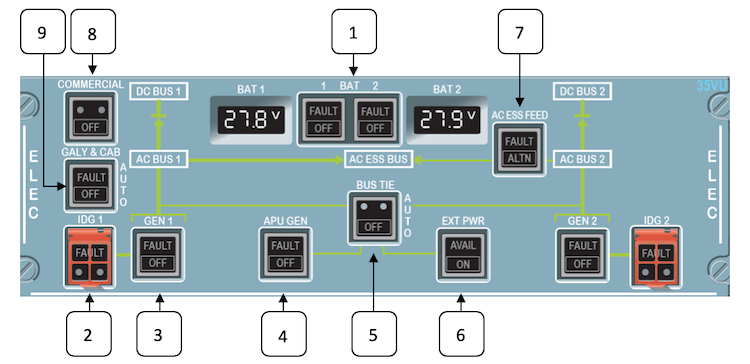
A320 Electrical Overhead Panel
NOTE
Click on the links above for more details.
EMER ELEC PWR OVERHEAD PANEL
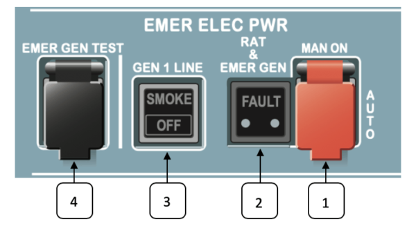
A320 Electrical Emergency Power Panel
NOTE
Click on the links above for more details.
normal operations
General
- Each engine generator supplies its associated AC bus.
- The APU generator can supply the entire network on the ground and, can be used as the sole source for all systems during flight excluding the galleys.
- One generator (engine or APU), is capable of supplying the entire network excluding the galleys.
- The external ground power can supply the entire network.
- Generators cannot be connected in parallel.
NOTE
Two generators are needed to supply the DC BUS Entertainment (if installed), except on ground, where the APU generator (if not overloaded) or the external power is sufficient.
Priority Logic
The priority logic determines which source is used. When that source is lost the system will automatically switch to the next available source.
- Engine Generators
- External Power
- APU Generator
- Ram Air Turbine (not simulated)
- Batteries
For example, if the aircraft is supplied by the APU generator and EXT PWR comes online, the system will automatically switch to EXT PWR but, when ENG GEN come online, the system will automatically switch to ENG GEN.
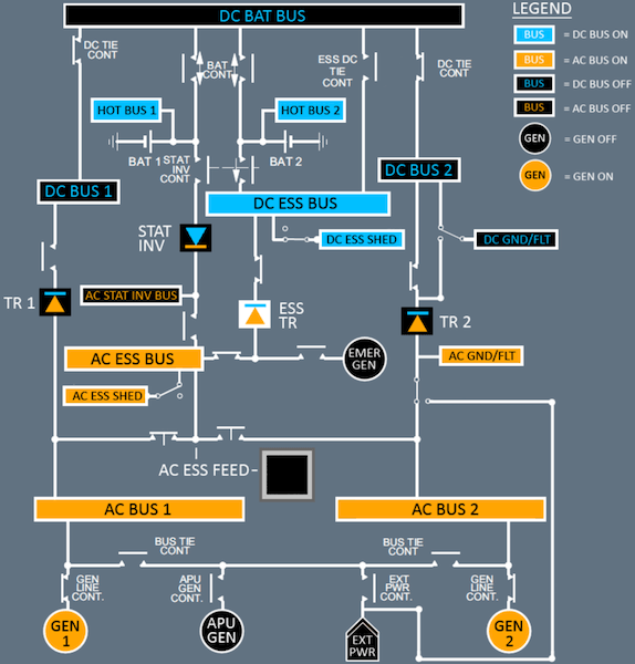
Normal Configuration
In Flight
- Each engine generator supplies its associated AC BUS via its Generator Line Contactor (GLC 1 & 2).
- AC BUS 1 supplies the AC ESS BUS via a contactor.
- TR 1 supplies DC BUS 1, DC BAT BUS, and DC ESS BUS.
- TR 2 supplies DC BUS 2.
- The two batteries are connected to the DC BAT BUS if they need charging. When they are fully charged, the Battery Charge Limiter disconnects them.
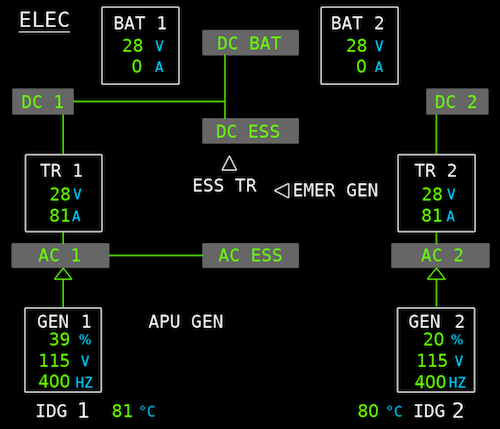
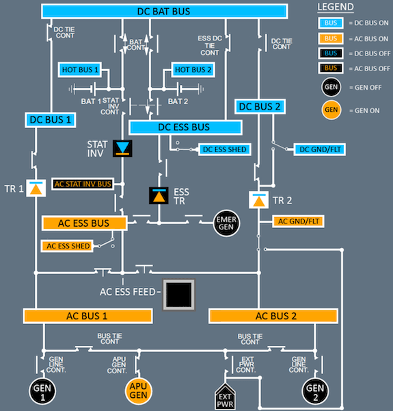
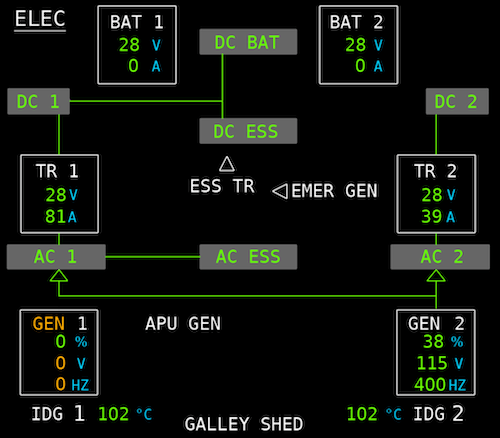
Normal Configuration in Flight.
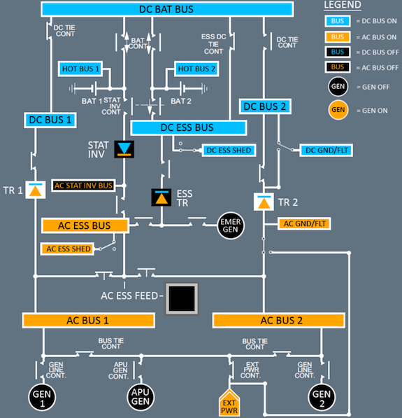
On Ground
Either the APU generator, or external power, may supply the complete system.
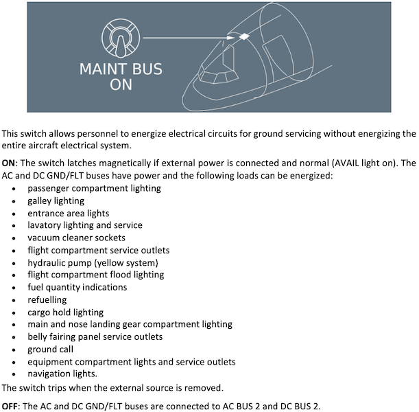
When only ground services are required, personnel can select the MAINT BUS switch in the forward entrance area to ON.
This allows to energize the AC and DC GND/FLT buses directly without supplying the entire aircraft network.
Check
here the systems that are supplied by the AC and DC GND/FLT buses.
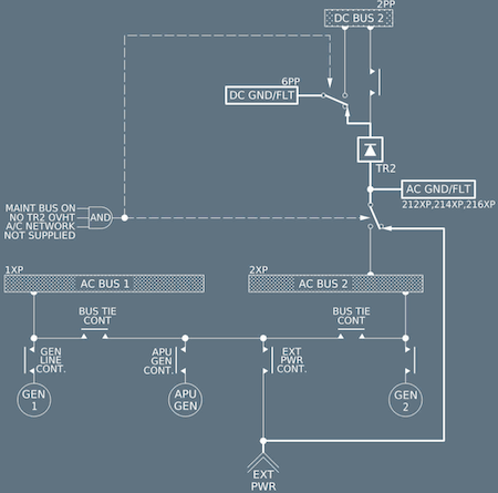
AC and DC GND/FLT buses
ABNORMAL OPERATIONS
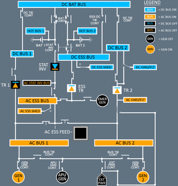
Failure of one Engine Generator
The system automatically replaces the failed generator, with the :
- APU GEN, if available, or
- Other engine generator.
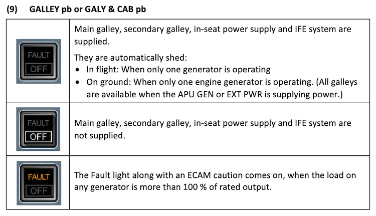
The DC BUS Entertainment (if installed) and part of the galley load are automatically shed.
NOTE
The Galley Load Automatic Shedding (if installed), allows all the galley load to be automatically shed.
Failure of one Generator.
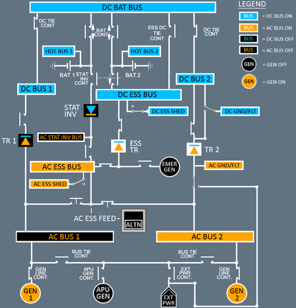
Failure of AC BUS 1
Normally, AC BUS 1 supplies the AC ESS BUS and via TR 1 the DC ESS BUS.
If AC BUS 1 fails:
- The AC BUS 2 automatically supplies the AC ESS BUS and via ESS TR, the DC ESS BUS.
- The DC BUS 2 supplies DC BUS 1 and DC BAT BUS automatically after 5 s.
Failure of one TR
The contactor of each TR opens automatically, in case of :
If one TR fails, the other TR automatically replaces the faulty one and the ESS TR supplies the DC ESS BUS.
Failure of TR 1 and TR 2
If both TRs are lost, the DC BUS 1, DC BUS 2, and DC BAT BUS are lost and the DC ESS BUS is supplied by the ESS TR.
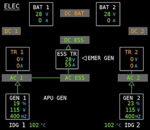
Failure of TR 1 and TR 2.