GENERAL
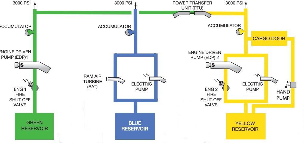
The aircraft has three continuously operating hydraulic systems; GREEN, BLUE and YELLOW. Each system has its own hydraulic reservoir. The normal operating pressure is 3000 psi (2500 psi when the BLUE system is powered by the RAT). Hydraulic fluid CANNOT be transferred from one system to another.
system description
Green Hydraulic System
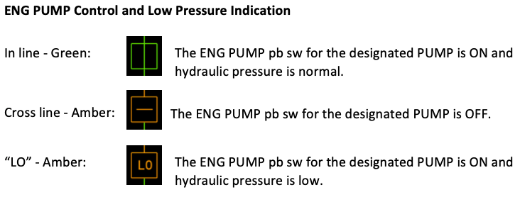
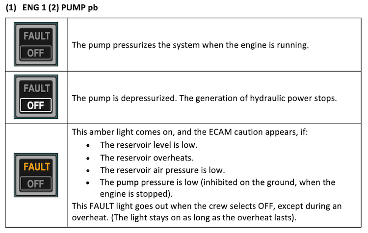
An engine pump, driven by engine No1 pressurizes the GREEN system.
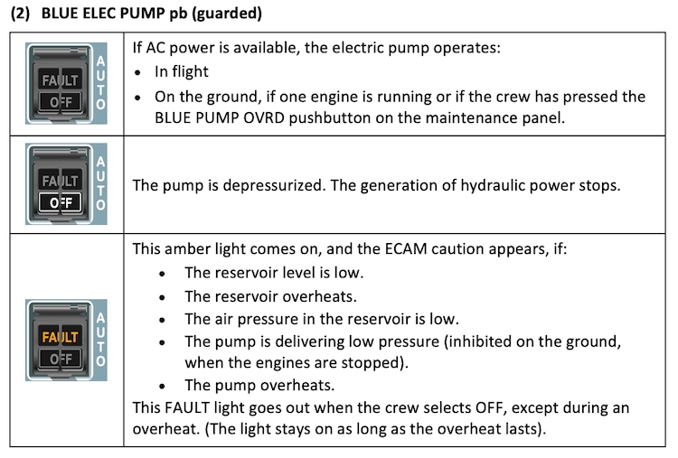
Blue Hydraulic System
An electric pump pressurizes the BLUE system. In case of emergency, a pump driven by a Ram Air Turbine (RAT) pressurizes this system. When AC electrical power is available and the electric pump pushbutton is at AUTO position, the BLUE system is automatically energized:
- In flight
- On the ground, if one engine is running or if the crew has pressed the BLUE PUMP OVRD pushbutton on the maintenance panel.
Yellow Hydraulic System
The YELLOW system is pressurized by:
- An engine pump, driven by engine No2.
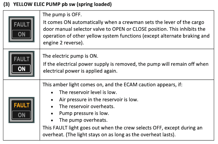
- An electric pump, in order to be used on the ground when the engines are stopped.
- A hand pump, to be used by ground staff when no electrical power is available in order to operate the cargo doors.
When we select the electric pump ON, the whole YELLOW system is pressurized and, via the PTU the GREEN system is also pressurized.
The electric pump comes ON automatically when a crewman sets the lever of the cargo door manual selector valve to OPEN or CLOSE position. This inhibits the operation of all the other YELLOW system functions except alternate braking and engine 2 reverse.
Hydraulic Power Generation
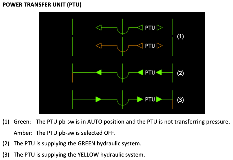
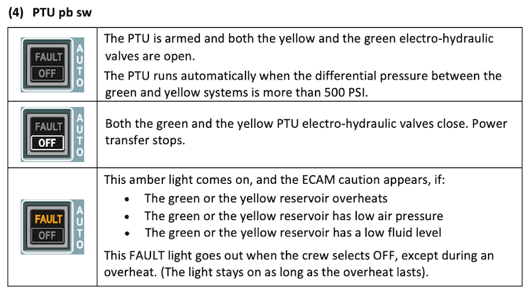
Power Transfer Unit (PTU)
A bidirectional Power Transfer Unit (PTU) enables the YELLOW system to pressurize the GREEN system and vice versa.
The PTU comes into action automatically when the differential pressure between the GREEN and the YELLOW systems is greater than 500 psi. This allows to cover the GREEN or YELLOW system loss in case of one engine failure or one engine driven pump failure.
In case of reservoir low level, reservoir overheat or reservoir low air pressure, the PTU must be switched OFF as required by ECAM to avoid a PTU overheat which may occur two minutes later and lead to the loss of the second hydraulic circuit.
On the ground with both engines stopped, when the YELLOW electric pump is selected ON, the automatic operation of the PTU allows also the GREEN system to be pressurized.
NOTE
The PTU is inhibited during the first engine start and automatically tested during the second engine start.
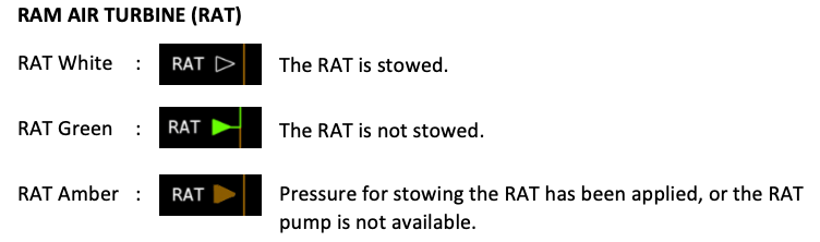
Ram Air Turbine (RAT)
When the RAT is extended, a hydraulic pump coupled to it, pressurizes the BLUE system. The RAT extends:
- Automatically, if AC BUS 1 and AC BUS 2 are both lost (e.g. total electrical failure or both engines fail) or,
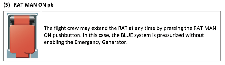
- Manually, if the crew presses the RAT MAN ON guarded pushbutton on the hydraulic overhead panel. In this case, the BLUE system is pressurized without enabling the Emergency Generator.
After being extended, the RAT can be stowed only when the aircraft is on the ground.
NOTE
The RAT does not extend automatically for any hydraulic failure.
System Accumulators
An accumulator in each hydraulic system helps to maintain a constant pressure by covering transient demands during normal operation.
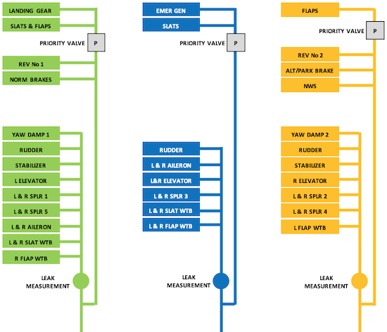
Priority valves
Priority valves cut off the hydraulic power to heavy load users if hydraulic pressure in a system gets low.
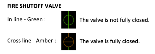
Fire Shutoff valves
Each of the GREEN and YELLOW systems has a fire shutoff valve in its line upstream of its engine-driven pump. The flight crew can close it by pushing the ENG 1(2) FIRE pushbutton.
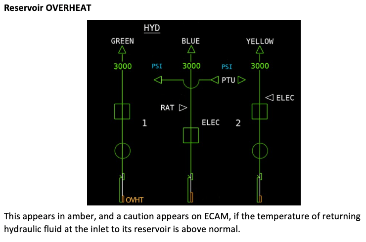
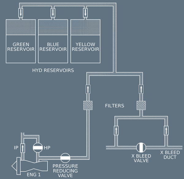
Reservoir Pressurization
The
Reservoir Pressurization on each hydraulic system is done automatically by high pressure bleed air from engine No1 in order to prevent pumps from cavitation. If the engine No1 bleed air pressure is too low, the system takes bleed air pressure from the crossbleed duct.
The probability of cavitation increases with altitude. If we lose a hydraulic system due to reservoir low air pressure, it may be possible to restore it after descending to a lower altitude.
DISTRIBUTION
A320 Hydraulic Distribution
hydraulic overhead panel
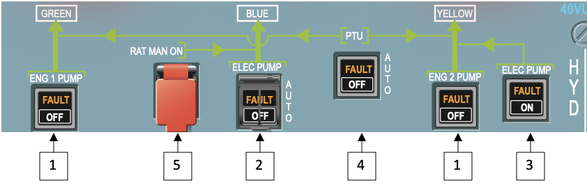
A320 Hydraulic Overhead Panel
NOTE
Click on the links above for more details.
ecam hydraulic page
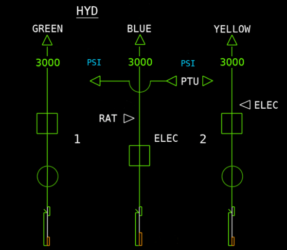
A320 ECAM Hydraulic Page
NOTE
Click on the links above for more details.
ABNORMAL OPERATIONS
General
Single hydraulic failures have very little effect on the handling of the aircraft but will cause a degradation of the landing capability to CAT 3 SINGLE.
Dual hydraulic failures however, although unlikely, are significant due to the loss of AP, flight control law degradation, landing in abnormal configuration and extensive ECAM procedures with associated workload and task-sharing considerations.
It is important to note that the AP will not be available but, both FD and A/THR still remain. Additionally, depending on the affected hydraulic circuits, aircraft handling characteristics may be different due to the loss of some control surfaces. The PF should manoeuvre with care to avoid high hydraulic demand on the remaining system.
A double hydraulic failure is an emergency situation, with red LAND ASAP displayed, and a MAYDAY should be declared. A landing must be carried out as soon as possible bearing in mind, however, that the ECAM actions should be completed prior the approach.
This failure is a "complex procedure" and the QRH summary should be referred to upon completion of the ECAM procedures.
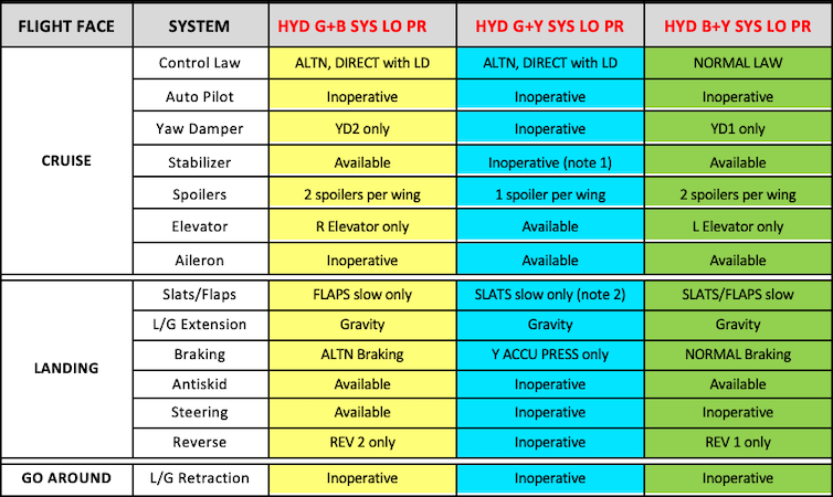
Remaining Systems
NOTE 1
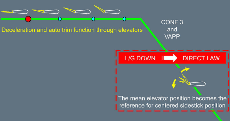
The stabilizer is lost. In alternate law,
the auto trim function is provided through the elevators. At landing gear extension, switching to direct law, the auto trim function is lost. However, the mean elevator position at that time is memorized, and becomes the reference for centered sidestick position. This is why, in order to ensure proper centered sidestick position for approach and landing, the procedure requires waiting for stabilization at VAPP, before landing gear extension.
If this procedure is missed, the flare and pitch control in case of go-around may be difficult. The PFD message USE MAN PITCH TRIM after landing gear extension should thus be disregarded.
NOTE 2
High pitch during approach should be expected. Approach briefing should outline it for tail strike awareness and pitch attitude will be monitored during flare.